|
|
|
Who's Online
There currently are 5642 guests online. |
|
Categories
|
|
Information
|
|
Featured Product
|
|
|
 |
|
|
There are currently no product reviews.
 ;
A comprehensive Operating and Service Manual. All schematics are complete and easy to read. The PCB drawings and complete parts list are very helpful. I would definitely recommend this manual.
;
SCANNING OF HIGH QUALITY
VERY, VERY HIGH VELOCITY DOWNLOAD
VERY GOOD PRICE,
TRUE SATISFIED, THANKS
;
Genuine Toshiba owner's manual. Couldn't really ask for more. And written in understandable English in contrast to a few recent experiences I have had with manuals for other equipment other than Toshiba but made in China and written in "Chinglish"!
;
I purchased a vintage Sony mixer off eBay and within the hour was able to locate and purchase the manual for it.I mean really,where else can you find a manual for a product made in 1983!? It was easy to find and purchase/download the manual I needed.I will use this site again for other equipment I have! Great site!
;
manual de usuario perfecto y completo de buena calidad de impresion y muy detallado ideal !
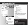
L3 AND L4 RECEIVER FEATURES AND CONTROLS (Figure 3)
FRONT
REAR MODEL L3 RECEIVER MODEL L4 RECEIVER L3 AND L4 RECEIVERS, EXTERNAL FEATURES AND CONTROLS
FIGURE 3 1. POWER ON Indicator: This green LED glows when power is turned on. 2. RF Signal Indicator (L3 Only): Yellow light glows to show that received RF signal exceeds squelch threshold level. This light is not an indicatorof signal strength, although a barely flickering light indicates marginally acceptable signals. 3. AUDIO PEAK Indicator: Red light glows to show approaching audio overload condition. Normal operation is shown by occasional glowing of light on loud signals; constant glowing indicates excessive audio level and need to lowertransmitter Audio Level control. 4. VOLUME Rotary Control: Determines signal level at receiver OUTPUT connector(s). Also permits matching signal level to input level requirements of a mixer or amplifier. 5. POWER On/Off Button: Applies power from the DC power input jack to the receiver. Green POWER light glows and remains on when power is applied to the receiver. DIVERSITY Signal Indicators (L4 Only): Yellow lights glow to 6. show usable RF signals are being received from antenna A, antenna B, or both. 7. AUDIO NORMAL Indicator (L4 Only): Green light flashes, showing normal audio operation. 8. Phone Jack Output Connector: ¼-inch phone jack provides unbalanced output to audio mixer or amplifier. 9. 12 VDC Negative Ground Coaxial Power Jack: Accepts power from the supplied AC adapter, or from any well-filtered 12-18 VDC supply. 10. SQUELCH MIN-MAX Screwdriver Control: The squelch circuit automatically quiets or �mutes� the receiver when no transmitter signal is being received. The squelch control is factory-set for best operation in most applications, but can be adjusted for unusual conditions (see Receiver Squelch paragraph). 11. XLR Output Connector (L4 Only): XLR connector provides balanced low-impedance microphone-level output. 12. Antenna Connector: SO-239 UHF-type connector provides connection to ¼-wave vertical antenna. RECEIVER SETUP L3 and L4 Receiver Installation 1. Place the receiver in its operating location, either on a horizontal surface or in a rack panel (rack panel mounting brackets are supplied with L4 receivers). If placed on a horizontal surface, attach the four adhesive bumpers to the bottom corners of the receiver. If installing an L4 receiver in a rack panel, remove the screws on each side of the receiver, position the mounting brackets supplied with the L4 over the holes, and secure the brackets with the two removed screws and the two screws supplied with the L4. 2. Connect the supplied PS20 AC adapter to the POWER input connector on the rear panel. Plug the AC adapter into a 120 VAC, 60 Hz power source. NOTE: If the receiver is to be plugged into a 230 VAC, 50 Hz power supply, connect the PS20E AC adapter to the POWER input connector on the rear panel. 3. Attach the supplied ¼-wave antennas to the ANTENNA connector(s). Make sure the antennas are pointed upward. IMPORTANT The receiver antenna(s) should be within line-of-sight of the transmitter. Obstructions or reflective objects will degrade system performance. Improved L4 diversity performance may be obtained by remotely locating one or both antennas so that they are separated by 1.5 meters (60 inches) or more. Optional Shure WA380 ½ Wave High Gain Antennas are recommended for such applications. They may be mounted directly on the receiver or remotely located using two Shure WA420 Antenna Cable Kits. With rack-mounted receivers, both antennas mustextend above the rack cabinet or be remotely located. To operate as many as four receivers with only two antennas, use the Shure WA404 amplified Antenna/DC Power Distribution System. 4. Obtain an audio cable (Shure WA410 or equivalent) with appropriate connectors to connect the receiver to audio mixer or amplifier. NOTE: To connect the L3 output to the high-impedance input of an audio mixer or amplifier, use a cable with ¼-inch phone plugs on both ends. 5. Connect the cable between the OUTPUT connector on the receiver and the mixer/amplifier input. NOTE: When a long cable run is required, or when the mixer input has phantom power present, add a low- to high-impedance line matching transformer at the L3 output jack (Shure A95U or equivalent). A conventional low-impedance microphone cable can then be used between the A95U output and the mixer input.
3
|
|
|
> |
|